
Great Solar Inverters and Chargers UK:
The Ultimate 2026 Guide
Choosing the right solar inverters and chargers is essential for converting sunlight into usable home energy.
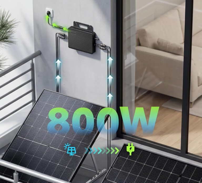
Whether you are setting up a legal 800W plug-in kit or a custom off-grid battery bank, the inverter acts as the ‘brain’ of your system. Our guide highlights high-efficiency, G98-compliant components designed for safety and longevity in the UK climate.
By investing in quality solar inverters and chargers, you ensure that every watt generated is delivered safely to your appliances, protecting your home electronics while maximizing your energy independence and long-term financial savings
Installation Best Practices
- Shade Management: Utilising dual-MPPT technology within your solar inverters and chargers (such as the APsystems EZ1-M) is critical if your installation area receives partial shade. This ensures that if one panel is blocked by a shadow, the other continues to generate at full capacity, protecting your overall energy harvest.
- Effective Cooling: Micro inverters should always be mounted in well-ventilated areas to prevent “thermal throttling.” This occurs when the unit overheats and reduces power output to protect its internal electronics. Ensuring a small air gap between the inverter and the mounting surface is a key step in maintaining the lifespan of your solar inverters and chargers.
- Regulatory Compliance: All DIY installations must follow the BS 7671 Wiring Regulations. This ensures your connection to the home grid is fire-safe and meets UK electrical standards. Remember that even for “Plug and Play” systems, your home’s existing ring main must be in good repair to handle the continuous load.
- DC Safety Disconnect: For maximum safety, we recommend installing a dedicated DC circuit breaker between your solar panels and the micro inverter. This provides a manual “Emergency Stop” point, allowing you to safely isolate the system for maintenance without having to reach behind active panels.
Battery Sizing & Safety
- Capacity Matching: For a 2000W inverter, we recommend a minimum 150Ah battery. For 3000W units, aim for 200Ah+ to prevent rapid voltage drops.
- Cable Thickness: High-power inverters draw massive current. Ensure you use a minimum of 25mm² battery cables to prevent overheating and fire risks.
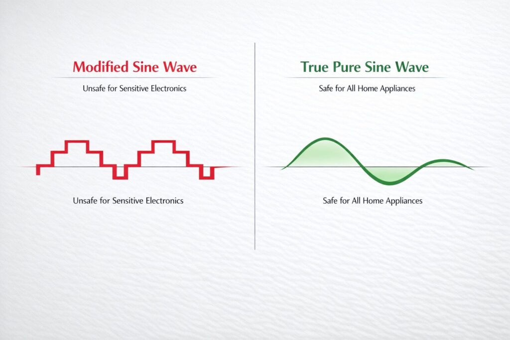
- Clean Power: Never use “Modified Sine Wave” inverters for home appliances; only Pure Sine Wave models are safe for modern household circuitry.
How to Choose Your Solar Inverters and Chargers
- Grid-Tie vs. Off-Grid: Use a Micro Inverter (like the 800W EZ1-M) if you want to plug solar directly into your home sockets. Use a Pure Sine Wave Inverter if you are building an independent battery backup system.
- The MPPT Advantage: Never settle for a cheap PWM charger. MPPT chargers act like an automatic gearbox for your solar panels, constantly adjusting to find the perfect voltage to keep your batteries healthy and topped up.
- Safety Standards: Always ensure your solar inverters and chargers are CE certified and feature safety protections for over-voltage and thermal shutdown. This is especially critical for indoor DIY installations in the UK.
- Shade Management: Use dual-MPPT inverters (like the AP systems) if your balcony gets partial shade. This technology ensures that a single shaded panel doesn’t reduce the total energy harvest of your entire array, maximizing the efficiency of your solar inverters and chargers.
- Cooling: Always mount inverters in well-ventilated areas to prevent thermal throttling. Maintaining constant airflow is vital to protect the sensitive internal electronics and ensures your system delivers stable AC power even during peak summer temperatures.
- Safety:
- All electrical installations must comply with the BS 7671 Wiring Regulations to ensure your home power setup is fire-safe and legally compliant.
- We highly recommend installing a dedicated DC circuit breaker between your panels and the inverter to provide an immediate manual disconnect point for emergency maintenance or grid-related faults.
Solar Inverter & Charger Buying Guide
What are Solar Inverters?
What are MPPT Charge Controllers?
An MPPT charge controller regulates power between solar panels and storage batteries.
Raw electricity from solar panels fluctuates constantly with passing clouds and shifting seasons.
Connecting a solar panel directly to a battery causes severe undercharging or permanent thermal damage.
The controller acts as a dynamic safety barrier that steps down high panel voltages to a safe charging level.
Standard regulators simply pull panel voltage down to match the battery.
This wastes vast amounts of potential energy. An MPPT unit recalculates the optimal voltage and current mix multiple times per second.
Where They Fit Into Your System
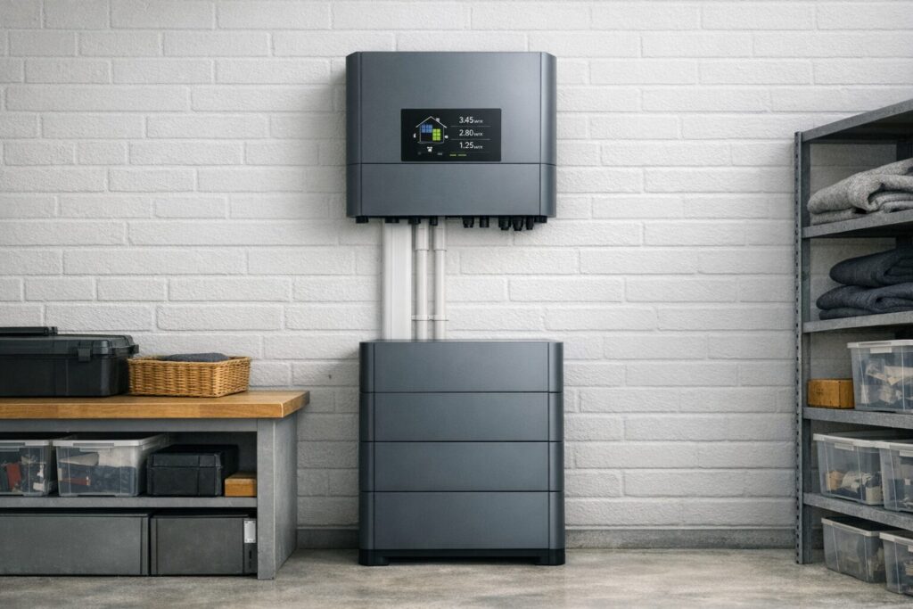
Off-grid backup systems require a centralized hub layout. The solar panels connect directly to the MPPT charge controller using heavy-duty DC wires.
The controller regulates this incoming power and feeds it straight into your battery storage bank. The standalone pure sine wave inverter then connects directly to those same battery terminals.
It pulls stored DC power from the cells and converts it to AC whenever your home appliances demand electricity.
Off-Grid System Energy Flow
800W Micro Inverters (G98 Compliant)
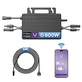
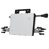
Designed for the DIY plug-in market, these 800W micro inverters convert DC power from your panels directly into 230V AC for your home sockets. We focus on units with dual MPPT inputs, allowing you to maximize generation even if one panel is partially shaded. These compact solar inverters and chargers offer an ideal entry point for UK homeowners, providing a scalable and efficient way to reduce reliance on the National Grid through a simple, safe, and immediate plug-and-play installation process
Pure Sine Wave Inverters for Home Backup




MPPT Charge Controllers: Maximising Efficiency
Efficiency is key when converting sunlight into stored energy. These solar inverters and chargers include advanced Maximum Power Point Tracking (MPPT) technology, which can harvest up to 30% more power than standard PWM controllers. We have selected the industry-leading models from Victron and Renogy because they offer precise charging profiles for LiFePO4 batteries and feature Bluetooth monitoring so you can track your energy flow from your phone


Inverter and Charger Technical Specifications Matrix
Evaluating solar hardware requires a strict comparison of electrical and thermal operating boundaries. Relying purely on retail naming conventions can result in mismatched components or systemic failures under full load. The data matrix below provides the exact mechanical, voltage, and environmental boundaries for the three core equipment categories used in modern domestic power installations.
| Technical Metric | 800W Micro Inverters (Grid-Tie) | Pure Sine Wave Inverters (Off-Grid Backup) | MPPT Charge Controllers (Solar-to-Battery) |
|---|---|---|---|
| DC Input Voltage Range | 16V to 60V DC | 9.5V to 16V DC for 12V setups or 21V to 32V DC for 24V setups | 15V to 100V DC up to 150V on heavy commercial units |
| AC Output Voltage and Waveform | 230V AC Single Phase Pure Sine Wave | 230V AC with less than 3 percent Total Harmonic Distortion | DC Output Only |
| Peak Operational Efficiency | 96.5 to 97.3 percent | 90 to 93 percent | 98.0 to 99.2 percent |
| Standby Power Consumption | Less than 50mW night time tare loss | 15W to 30W constant idling draw when active | Less than 1W standby draw |
| Primary Cooling Mechanism | Passive natural convection via external cooling fins | Active temperature controlled internal extraction fans | Passive cooling or active fans on high amperage units |
| Environmental Protection Rating | IP67 or IP68 fully weatherproof for outdoor mounting | IP20 indoor use only with open ventilation pathways | IP20 or IP21 indoor mounting only |
| Core Protective Fail Safes | Anti islanding protection with over and under frequency trips | Low voltage shutdown and over temperature thermal throttling | Over voltage clamping and reverse current night isolation |
Component Sizing & Cable Gauge Reference Guide
| Installation Setup | Peak Current Draw | Target DC Cable Size | Minimum Overcurrent Fuse | Safe Battery Limit |
|---|---|---|---|---|
| 800W Micro Inverter Array | 13A per panel channel | 4mm² cross section PV wire | 15A inline MC4 fuse links | N/A direct grid tie connection |
| 2000W 12V Standalone Backup | 185A maximum continuous draw | 35mm² to 50mm² copper cable | 250A mega fuse blocks | 150Ah lithium iron phosphate minimum |
| 3000W 24V Heavy Home Storage | 135A maximum continuous draw | 50mm² flexible welding specification | 175A ANL bolt down fuse | 200Ah lithium iron phosphate minimum |
| 40A MPPT Charging Pipeline | 40A continuous charge output | 10mm² copper connection wire | 50A midi inline battery fuse | Matches specific controller maximums |
If you are setting up a standalone system or emergency homestead backup loop that relies on a portable combustion engine alongside your storage bank, make sure to cross-reference our complete performance breakdown on Inverter Generators.
The Science of Power Inversion: DC to AC Pure Sine Waves
How MPPT Algorithms Outperform Standard PWM Units
| Performance Characteristic | Pulse Width Modulation (PWM) | Maximum Power Point Tracking (MPPT) |
|---|---|---|
| Average Energy Efficiency | 70 to 75 percent | 95 to 99 percent |
| Real World Power Gain | Baseline performance | 15 to 30 percent more power harvested |
| Performance in Overcast Weather | Poor drop-off when panel voltage falls | Excellent adjusts instantly to low light conditions |
| Array Configuration Flexibility | Panels must match battery voltage perfectly | Supports high voltage panel strings for long runs |
| Suitable Installation Scale | Small campervans or simple trickle chargers | Domestic home backup systems and arrays over 150W |
Multi-Stage Battery Charging Cycles (Bulk, Absorption, Float)
Phase 1: The Bulk Charging Stage [Expand]
Phase 2: The Absorption Charging Stage [Expand]
Phase 3: The Float Charging Stage [Expand]
Managing Thermal Performance and Avoiding Thermal Throttling
Power conversion components handle high currents and generate significant heat during normal operation. Inverters and chargers use internal circuits that track component temperatures in real time to prevent critical heat damage. When temperatures cross specific thermal thresholds, the hardware automatically engages fail-safe measures to cool the system down.
Understanding Thermal Throttling [Expand]
Common Symptoms of System Overheating [Expand]
Ventilation and Installation Best Practices [Expand]
BS 7671 Wiring Regulations & Home Grid Integration
Integrating high-power energy generation hardware into a residential property requires strict compliance with UK electrical safety frameworks. Domestic installations must align thoroughly with BS 7671 regulations, also known as the IET Wiring Regulations. These rules ensure that all hardware can safely manage fault currents, prevent systemic fires, and isolate automatically during emergencies.
Protective Earthing Requirements [Expand]
Type B RCD Selection Criteria [Expand]
Automatic Disconnection and Isolation Standards [Expand]
G98 vs. G99 Grid Notification Requirements
| Regulatory Parameter | G98 Notification Framework | G99 Application Framework |
|---|---|---|
| Maximum Inverter Output Capacity | 16A per phase up to 3.68kW single phase or 11.04kW three phase | Exceeds 16A per phase over 3.68kW single phase or 11.04kW three phase |
| Process Timeline Required | Fit and Inform notify the operator within 28 days after commissioning | Apply and Wait obtain written approval prior to commencing installation |
| Typical Equipment Profile | Small 800W plug in arrays and compact micro inverters | Large full home storage arrays and high capacity hybrid systems |
| Network Operator System Fees | Zero application fees for standard compliant hardware | Variable network assessment fees and potential reinforcement costs |
| Network Technical Constraints | Minimal assessment if inverter holds type tested certification | Stringent network fault level evaluations and witness testing limits |
Essential Safety Hardware: DC Isolators and Circuit Breakers

In tandem with mechanical rotary isolators, you must integrate dedicated DC circuit breakers along your high-amp battery supply runs. Standard domestic AC miniature circuit breakers will fail to extinguish a high-current DC fault arc and must never be substituted. Using a properly rated double-pole DC breaker provides essential short-circuit protection and serves as a rapid physical disconnect link if you ever need to service your storage cells.
Integrating Inverters with Solar Cables and Surge Protectors
Telemetry Tracking: Connecting to Solar Energy Monitors
FAQ
Can I connect an off-grid inverter directly to my main household consumer unit? [Expand]
- No, grid-linked setups must stay completely separate.
- Direct terminal hookups risk dangerous home grid backfeeding.
- Install an approved dual-pole changeover switch instead.
- Wire it with heavy-gauge Solar Cables and Connectors.
- This prevents low-voltage cutout trips under heavy loads.
What happens if panel voltage exceeds the maximum DC input limit of my controller? [Expand]
- Exceeding maximum open-circuit limits causes instant component failure.
- High voltage punches straight through internal switching transistor barriers.
- This damage remains entirely irreversible and voids warranties.
- Always calculate string voltages based on lowest winter temperatures.
Why does my inverter buzz loudly or run hot under load? [Expand]
- Excessive noise indicates high harmonic distortion inside coils.
- Modified sine wave variants stress sensitive electronic components.
- Upgrade to premium pure sine wave devices to solve this.
- Ensure structural mounting zones provide ample cooling airflow clearances.
How do I protect my inverter from external grid switching spikes? [Expand]
- Install dedicated transient voltage shunts on incoming lines.
- These safety systems capture spikes before reaching microchips.
- Integrate a matching module via Solar Surge Protectors.
- This locks down complete hardware safety across your installation.